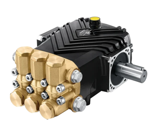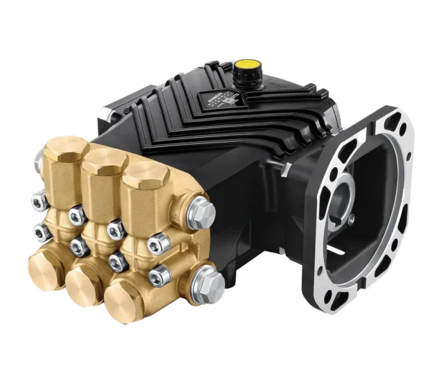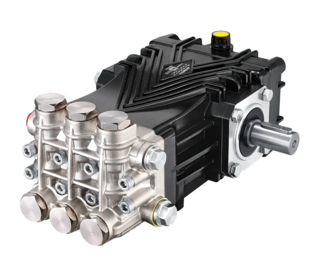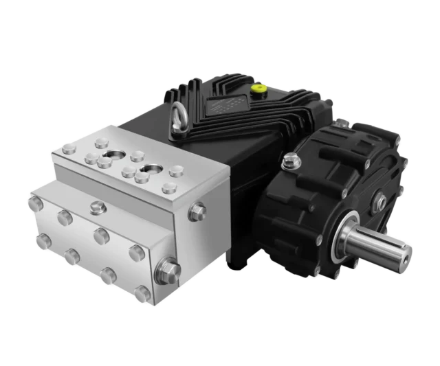
An OEM pump selection is a system design decision. Define the operating envelope, liquid, drive, controls and installation interfaces before choosing a model code.
Write a duty sheet
State pressure needed at the nozzles or process, line losses, simultaneous outlet flow, daily duty, water temperature and quality, supply conditions and control sequence. Identify minimum and maximum operation, not just one nominal point. A series' maximum pressure and maximum flow may belong to different models.
Close the flow and power balance
Hydraulic power is Pₕ (kW) = p (bar) × Q (L/min) ÷ 600. Required shaft power is Pₕ divided by pump overall efficiency at that duty; include transmission losses separately. Motor or engine selection must cover the permitted envelope and transient requirements.
Consider two size 05 nozzles passing approximately 14 L/min each at 150 bar. Together they need 28 L/min. If a pump supplies 30 L/min, the additional 2 L/min needs a designed bypass or speed-control solution; calling it a wear allowance does not remove it from the balance.
If all 30 L/min passes through those nozzles, their estimated pressure rises to 150 × (30/28)² ≈ 172.2 bar before line losses. Conversely, a design that truly operates at 170 bar pump pressure and 30 L/min requires about 9.66 kW at the shaft with assumed efficiency 0.88, so an 11 kW motor may be considered after other checks. At 200 bar and 30 L/min, demand becomes about 11.36 kW: that same motor cannot simply be assumed adequate.
Match speed and mechanical interfaces
Delivered flow is approximately proportional to speed under comparable conditions, but use the model's permitted speed and lubrication range. Do not assign all D or E pumps one low-speed limit or promise a fixed life increase from reduced rpm.
Torque T (N·m) ≈ 9550 × P (kW) ÷ n (rpm). At 30 kW this gives about 198 N·m at 1450 rpm and 382 N·m at 750 rpm. Shaft suitability also depends on material, keys, fatigue and external loads. Equal shaft diameters do not prove drop-in compatibility: confirm flange, shaft extension, mounting, alignment, rotation and service access using drawings.
Select materials and inlet arrangements
Check every wetted material, seal and valve against the liquid, concentration, temperature and pressure. Ceramic is not universal across the Fussen range; FES and FES-G parts documentation lists an alloy plunger. Use actual performance tables and part references rather than decoding a model name as an exact specification.
Confirm minimum and maximum running inlet pressure, allowable temperature, pipe losses and dynamic filling requirements. Select a tank or booster from those conditions. Specify actual filter opening or micron rating, efficiency and clean/dirty pressure loss; mesh count is a different measurement. A universal 1–4 bar inlet rule is not a substitute for the model data.
Design pressure control and protection together
Valves must meet pressure and flow ratings simultaneously, as well as temperature, medium and response requirements. Distinguish a regulating valve, an unloader and independent overpressure protection. Set protection from the complete system's permitted limits and applicable design requirements, not a generic percentage above working pressure.
High-pressure bypass and low-pressure unloading have different heat loads. For water throttled through a pressure drop with energy converted approximately to heat, ΔT ≈ Δp/(ρcₚ): a 200 bar drop gives about 4.77°C per pass, and 1000 bar about 23.87°C. These simplified estimates are not constant pump temperature rises or allowable idle times. Total heating also depends on flow, circulating volume, return routing and cooling.
Verify the assembled machine
Review normal operation, outlet closure, low supply, temperature rise, emergency stopping and restart with the responsible system designer. Document approved settings, component ratings, drawings and service parts. Confirm the selected Fussen model against the complete duty sheet before release.
Related equipment
References and product documents
Frequently asked questions
Can I choose a valve by flow alone?
No. Pressure, flow, temperature, fluid compatibility and control behaviour must all match the system.
Is excess pump flow simply spare capacity?
Only if the system manages it. Fixed nozzles require a corresponding pressure, so excess flow needs an appropriate control or bypass arrangement.
Does a matching shaft diameter make a pump interchangeable?
No. Check mounting, shaft geometry, rotation, loads, alignment and the hydraulic duty as well.

Fussen has designed and manufactured high pressure plunger pumps and industrial washers in Foshan, China since 2001. ISO 9001 / 14001 / 45001, CE and ATEX-certified, exporting to more than 60 countries.