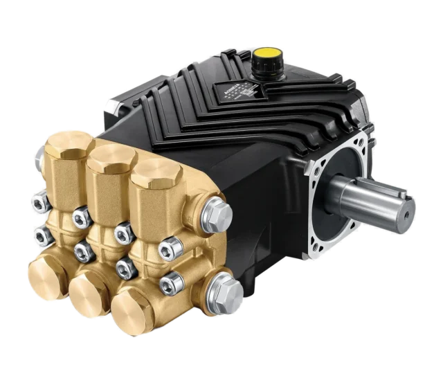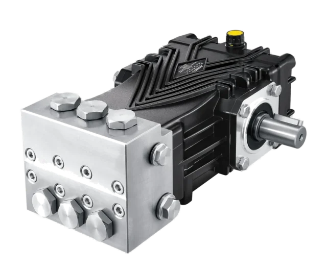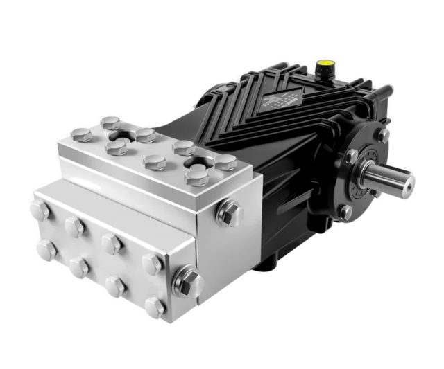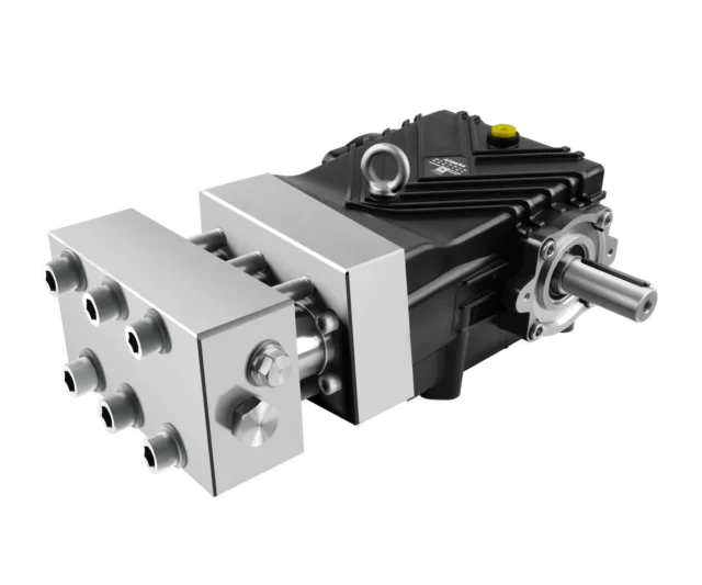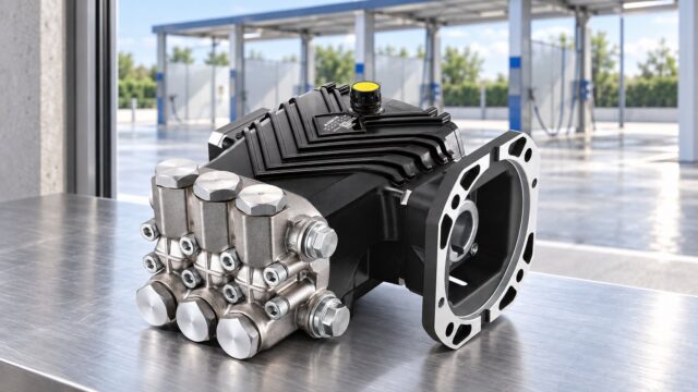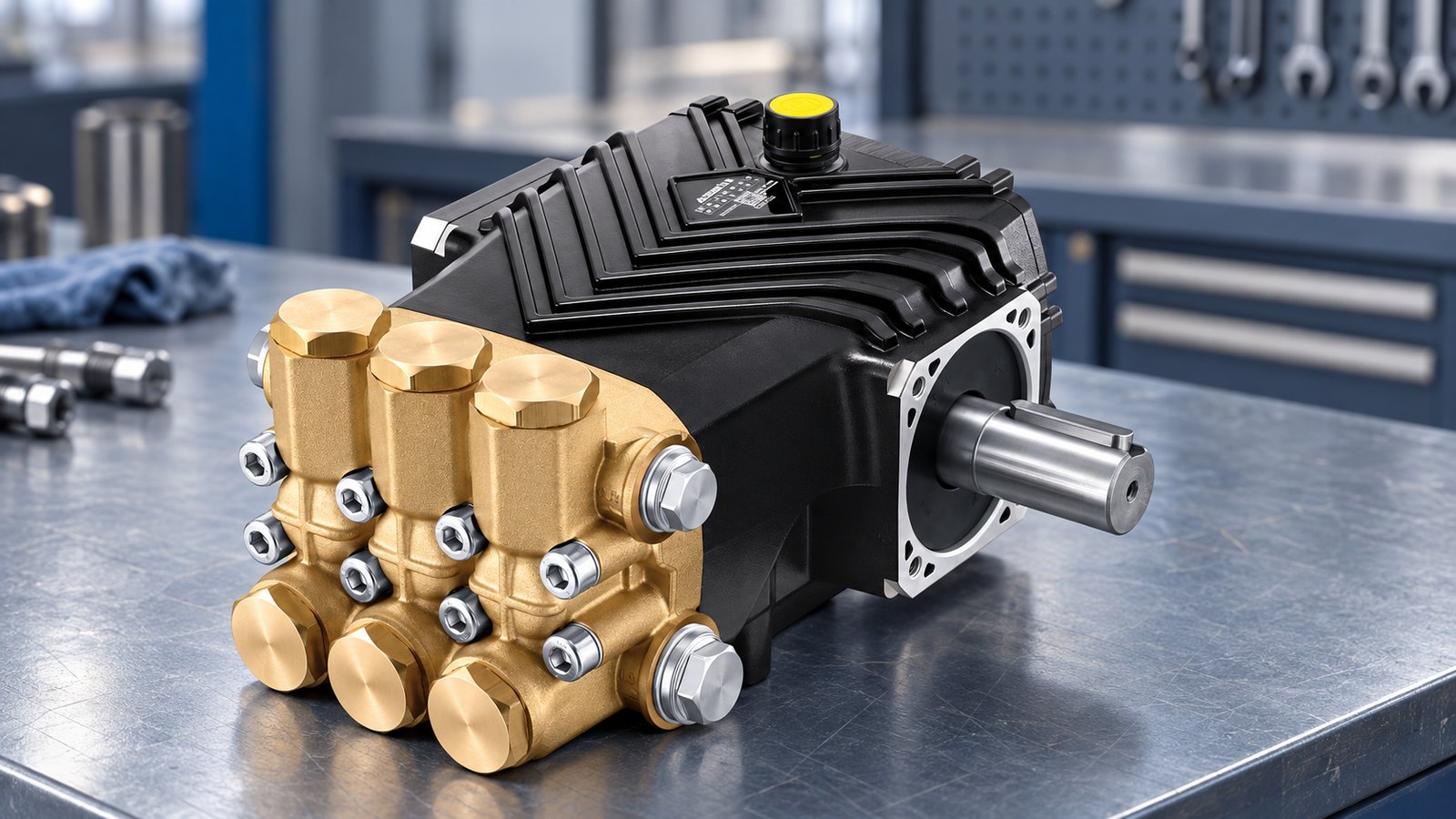
A triplex pump uses three reciprocating plungers to deliver pressurised water. Understanding displacement, valves and losses helps explain both performance and faults.
From shaft rotation to water flow
The crank mechanism converts shaft rotation into reciprocating motion. The three crank throws are phased 120° apart. During suction, an inlet valve admits water; during discharge, the inlet valve closes and the outlet valve opens when cylinder pressure exceeds outlet pressure.
In a plunger pump, the pressure packing remains in the liquid end while the plunger moves through it. In a conventional piston arrangement, the pressure seal moves with the piston. Actual bearing, guide and valve construction should be checked against the model's sectional drawing.
Why three plungers reduce pulsation
In the simplified model of three positive half-sine discharge flows spaced 120° apart, total flow varies approximately +4.72% and −9.31% around its mean. Peak-to-peak fluctuation is about 14.03% of mean flow. These are ideal kinematic values, not guaranteed measured performance.
Connecting-rod geometry, valve motion, leakage, water compressibility and piping change the real waveform. Pump flow pulsation is not the same as pressure pulsation at the gun. A damper must be selected for the system; hose length alone is not a performance specification.
Calculate displacement and delivered flow
For three single-acting plungers, Qₜ (L/min) = 3 × (πd²/4) × s × n ÷ 1,000,000, with bore d and stroke s in mm and speed n in rpm. Actual delivered flow is approximately Qₜ × ηᵥ, using volumetric efficiency for that operating point.
With d = 18 mm, s = 16 mm and n = 1450 rpm, theoretical flow is about 17.71 L/min. A catalogue value described as “up to 99.8%” must not be used as a fixed efficiency for every model and pressure.
Calculate shaft power separately
Pₕ (kW) = p (bar) × Q (L/min) ÷ 600. Divide hydraulic output by pump overall efficiency to estimate shaft power. At 17.7 L/min and 250 bar with assumed efficiency 0.90, about 8.19 kW is required. A 7.5 kW motor is therefore insufficient for that exact continuous duty.
Materials and speed are model-specific
Ceramic plungers are used in many washer pumps, but solid ceramic, ceramic sleeves and alloy plungers are different constructions. Fussen's FES and FES-G parts manual lists alloy plunger 7.906-158. Confirm the supplied model and revision rather than describing the entire range as ceramic.
Select head material and seals for pressure, temperature and fluid compatibility. Stainless steel is not a universal chemical-resistance guarantee. Nor does a series letter determine speed: some D-series catalogue ratings are at 1450 or 1750 rpm. Follow the actual model's speed and lubrication limits.
Use symptoms to guide checks
Reduced flow or pressure can result from poor inlet conditions, air, valves, seals, bypass leakage or nozzle wear. Check speed and supply first, then follow the model's service procedure. A percentage flow loss alone does not identify one failed component or prove that a seal kit is due.
Related equipment
References and product documents
Frequently asked questions
Is the quoted pulsation an operating limit?
No. The +4.72%/−9.31% values describe an ideal half-sine flow model. Real pressure and flow pulsation require system-specific assessment or measurement.
Are all Fussen plungers ceramic?
No universal claim should be made. FES and FES-G documentation lists an alloy plunger; verify the construction and part number of the supplied model.
Can a pump run slower than its catalogue speed?
Only within the permitted range. Confirm lubrication, inlet conditions and any drive restrictions; flow generally changes approximately with speed at a comparable operating condition.

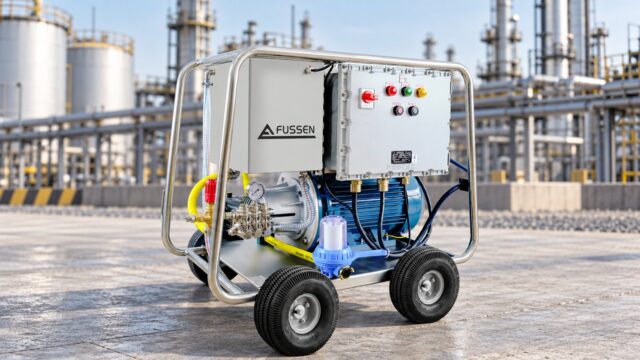
Fussen has designed and manufactured high pressure plunger pumps and industrial washers in Foshan, China since 2001. ISO 9001 / 14001 / 45001, CE and ATEX-certified, exporting to more than 60 countries.